Hex editing a battery controller
Can we avoid paying $400 apiece for replacement batteries, and instead just use $20 of 9 V batteries?
The Problem🔗
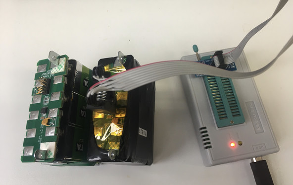
The SIM928 is an isolated voltage source using rechargeable 9 V batteries. Battery cells have ultra low noise, and when properly designed, voltage sources such as this one can provide a tunable output voltage independent of the cell voltage, and can be computer-controlled. The source uses two banks of batteries, charging one while the other provides the working voltage. Typical applications include bias voltages for precision analog instrumentation. The controller keeps track of the battery status via a separate 24LC16B EEPROM on the replaceable battery packs that tracks their charge/discharge cycles. Rechargeable batteries are rated for a finite number of charge cycles; this source specifies 1000 cycles which is not too bad. Removing the shrink wrap and tape around the battery pack shows that the 9 V batteries are readily replacable, but the device’s control API does not allow for resetting the cycle count in the EEPROM. This leads the controller to think the batteries need to be replaced, and the sources eventually stop working correctly. Earlier attempts to circumvent this counter didn’t work well (and unfortunately, any details are lost). We would like a nice, permanent solution to refurbish and reuse these battery packs. Replacement battery packs from the vendor are $400, and six replacement NiMH 9 V batteries are less than $20. We have several dozen of these voltage sources which require replacement every few years, so this would be quite a money-saver for the lab.
Approach🔗
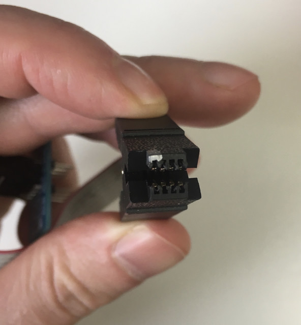
The EEPROM is accessible either via the pinout on the battery pack’s 10-pin connector, or, since it’s on the outside of the pack’s PCB, it can be directly accessed via a clip that clamps onto the SOIC-8 package in situ.
Rather than rigging up some Arduino, I wanted to use a purpose-build programmer.
I have one of the well-known Chinese ROM programmers, the XGecu 866II Plus.
It can be used with the vendor’s proprietary GUI program on Windows, but thankfully
the open-source minipro software can be used instead.
Initial exploration🔗
We can read the EEPROM with the programmer using whatever software you choose.
I have a Windows computer for this kind of lab work, so I just used the GUI.
It will save the memory contents as a .bin file.
While there are many programs spanning a huge degree of complexity that will let
you work with this data, I’ll stick to the simplest ones. Even on Windows, I usually
end up using Linux tools via WSL2 anyway, so this procedure will work for anyone regardless of platform.
We will read the memory to a .bin file, then use the xxd program to generate
a hex dump.1
(The xxd program is packaged on its own, or often with vim.) It’s
superior to the POSIX hexdump utility in that it can also work in reverse,
i.e. you can modify the hex dump in a text editor, and convert it back to a new
binary with xxd -r.
A well-used battery pack, with replacement batteries installed, yields the following hex dump. Most of it is empty, but the first two lines seem important:
xxd memory1.bin | head -n 2

00000000: 006e f063 0005 0006 07e0 0001 0001 59d8  .n.c..........Y.
00000010: 7c38 009b 03e8 ffff ffff ffff ffff ffff  |8..............
Another battery pack with factory batteries yields:
xxd memory2.bin | head -n 2

00000000: ff00 ffff ffff ffff 00e2 0001 0001 59d8  ..............Y.
00000010: 7c38 009b 03e8 ffff ffff ffff ffff ffff  |8..............
I know that the ROM holds the number of battery charge cycles, the design maximum number of cycles,
plus model number, serial number, and date of manufacture. The design maximum number
of cycles is 1000, which we see immediately as 0x3e8, but it’s not clear where
the rest of the information is, and why the two examples differ so much.
Simple awk script to examine the hex dump🔗
This will convert each 16-bit word into a decimal integer, to help us hunt for known numbers.
Save the following script as int16.awk:
# int16.awk - Interpret hex dump as 16-bit integers

BEGIN { ORS="" }

{
    for (i = 2; i <= 9; i++) {
        # strtonum is a gawk extension
        print strtonum("0x" $i) "\t"
    }
    print "\n"
}
Now we can examine the hex dump using the script. We’ll
pipe the output into less to help us look around the file. Press q to quit.
xxd memoryN.bin memoryN.hex
awk -f int16.awk memoryN.hex | less
Used on #1, this suggests the date is also on the first line, but we’ll need to work smarter to find out more. #2 has lots of equivalent areas masked out, what’s going on?
Known device queried by control code🔗
This time, we’ll use a battery module whose state we know because we’ve queried it while plugged into the voltage source, communicating to the controller over a serial port. This should help us decipher the memory.
xxd memory3.bin | less

00000000: 027b ebd8 0005 0006 07e0 0001 0001 59d8  .{............Y.
00000010: 7c38 009b 03e8 ffff ffff ffff ffff ffff  |8..............
[...]
00000100: 32ce 00c4 00c4 00c3 00c4 002f ffff ffff  2........../....
[...]
Using known values, we find the part number 635 at address 0x0;
the month, date, and year of manufacture 05/06/2016 at 0x4, 0x6, and 0x8;
and the design number of cycles 1000 at 0x12.
The control code gives 5160 as the serial number, but we have noticed in the past
that sometimes negative serial numbers were reported, and there is probably some confusion. Indeed, there is some implicit 2’s
complement interpretation of this 16-bit number somewhere along the line. If
we put a minus sign in front, and add 216,
we get -5160 + 2^16 = 60376 = 0xebd8, which we see at address 0x2.
The used cycle count 0xc4 is somewhat confusing, since it (or a number off by 1)
appears four times at 0x102, 0x104, 0x106, and 0x108. There are two battery
assemblies in the pack, so it makes sense that there would be two (and the manual confirms
that indeed the two assemblies may differ by a few cycles), but not why there are four entries.
While the vast majority of the 2 kiB memory dump is empty, there are some nearby bits that look
like information that we’ve yet to decipher.
Checking in on the battery state🔗
Revisiting the manual, we find commands to query the battery’s state. The two battery assemblies A and B can be in one of three states, (1 in use, 2 charging, 3 standby), and a separate service flag (0 okay, 1 service needed). I’ll denote this state by the tuple (Ax, By, Sz), where x, y, and z are numbers.
Looking at #3, can we ID these bits anywhere? This time, I’ll use xxd to give a binary
dump instead of a hex dump, since the alignment of the two- and one-bit signals is unclear.
To do so, we use the -b flag, and set eight columns with -c 8 to make it more-or-less
align with the hex dump:
xxd -b -c 8 memory3.bin | less
From the first dump of #3, this looks like (with relevant bits indicated with arrows):
          |||||||| ||||||||
          vvvvvvvv vvvvvvvv
00000100: 01100110 11001000 00010100 00110011 00010100 00110110 00010100 00100100
00000108: 00010100 00101001 00000000 01001101 11111111 11111111 11111111 11111111
                                     ^^^^^^^^
                                     ||||||||
We then returned the battery module to the controller, and checked the state via serial to find it in (A2, B0, S1). Then, we pulled out the battery module and dumped the memory again. It’s not clear that either of the memory dumps corresponds to the state we queried, although the first region didn’t change, and the second did.2
From the second dump, #3b, it looks like:
          |||||||| ||||||||
          vvvvvvvv vvvvvvvv
00000100: 01100110 11001000 00010100 00110111 00010100 00111010 00010100 00100111
00000108: 00010100 00101100 00000000 01001110 11111111 11111111 11111111 11111111
                                     ^^^^^^^^
                                     ||||||||
There is not quite enough information to tell, so let’s take a few more examples…
#4, which is in state (A3, B1, S0):
00000100: 01011101 00001010 00000001 00011010 00000001 00011010 00000001 00011010
00000108: 00000001 00011010 00000000 01000010 11111111 11111111 11111111 11111111
#5, which is in state (A2, B0, S1):
00000100: 01000101 11001111 00000011 11011101 00000100 00000101 00000011 11011001
00000108: 00000110 00000011 00000000 00111010 11111111 11111111 11111111 11111111
It’s not so clear to me what the pattern is, or even if it’s consistent between when we query the live device and when we dump the ROM. Let’s note that these particular regions of memory are volatile, and probably store the state somehow. Let’s hope additionally that we don’t need to know how it’s stored, and that the controller will properly manage that state for us.
Format🔗
Memory layout🔗
The 2 kiB memory is all 0xffff unless otherwise noted.
All uppercase letters denote decoded areas of memory,
explained in the table below.
00000000: PPPP SSSS MMMM DDDD YYYY 0001 0001 59d8
00000010: 7c38 009b LLLL ffff ffff ffff ffff ffff
...
00000100: VVVV CCC0 CCC1 CCC2 CCC3 00WW ffff ffff
...
00000200: 0000 ffff ffff ffff ffff ffff ffff ffff
Meanings🔗
| Field | Meaning | Note |
|---|---|---|
PPPP |
Part number | Always 0x27b |
SSSS |
Serial number | See 3 |
MMMM |
Month | |
DDDD |
Day | |
YYYY |
Year | |
VVVV |
Unknown, battery state | Volatile, ignore |
WW |
Unknown, battery state | Volatile, ignore |
LLLL |
Design life battery cycles | Always 0x3e8 |
CCCN |
Used battery cycles N=0-3 | Reset to 0x1 |
Unknowns🔗
- Fields
VVVVandWWpresumably store the battery’s state, and change quickly during use. - The 8 bytes of constant info starting at
0x10(betweenYYYYandLLLL) seem not to change. What do they mean?
Quirks🔗
Battery packs #1 and #2 have something written at every multiple of 0x100,
including at 0x0 and therefore corrupting the part number. I
suspect their memories are corrupted from the initial attempt to fix
the counter problem. These battery packs should probably be hand-flashed
to a full “clean” memory layout based on another example (the serial
number in #1’s case is also lost).
Tests🔗
Knowing the above memory table, let’s try to reset the counter and even do a full refurbishment, replacing batteries as well as resetting the counter and date in the memory.
Reset counter🔗
Let’s take a good battery pack, and reset its counter. This avoids dealing with taking a battery pack from a bad or “service” state to a good state, and any of the complications we might encounter with bad batteries, etc. We want to just change one thing and see if the module still accepts the battery pack. The best candidate is #4, which has 282 cycles. Let’s reset it to 1. We edit the hex and manually verify that our new binary looks good when re-dumped:
-
Save the hex dump to a file
xxd memory4.bin memory4.hex -
Edit the hex file, changing the fields
CCC0throughCCC3above to0x0001. Just change the hex in the middle, don’t worry about the ASCII representation to the right. It’s lossy and will be disregarded in the next step anyway. -
Convert the edited hex dump to a new binary file (
-rrunsxxdin “reverse”)xxd -r memory4.hex new4.bin -
Examine the new binary to make sure everything looks okay. Besides specific details, you’re looking to make sure the overall “shape” of the hex dump looks okay; usually the most common mistakes will completely garble or misalign everything compared to what the original looked like
xxd new4.bin | less -
Flash the EEPROM of #4 with
new4.binand observe behavior
After initialization, the count has incremented from 1 to 4. Perhaps this number shouldn’t be taken literally. The battery pack initializes, passing through the state (A2, B0, S0) until settling for a few minutes in state (A0, B2, S0) to charge battery B. This is initially confusing, since A0 and B0 are not specifically listed as valid states in the manual. After a few minutes, it switches to state (A1, B3, S0), which is normal operation, with battery A in use and battery B charged and on standby.
This initialization was confusing since it does not match what happens under normal operation, which is to failover to the second battery while charging the first, and vice versa (never using the state 0 for either battery). It seems that the initialization procedure is different, in that it serially charges each battery in turn, before entering normal operation.
Full refurb🔗
To test the full refurbishment procedure, we select battery pack #5, which was in the S1 service state and needed its batteries replaced. We replace the batteries with new ones and reflash the EEPROM with counters reset to 1 and today’s date. We used battery pack #5 to verify that the controller can properly manage updating the state of the batteries in the EEPROM on its own. This worked as well, although since the batteries are new, it will initially be stuck charging battery A (and then B) for some time before becoming fully operational.
Outcome🔗
We can now confidently refurbish our voltage source battery packs, having deciphered enough of their memory format to properly reset their use counters. On the hardware side, we need to duplicate this setup for the lab (as the programmer is my personal property), and build a foolproof programming cable to use the battery pack’s built-in ten-pin connector. A few units might need some more careful manual intervention due to corrupted memory from previous attempts to fix the problem, but it should be easy to boil this procedure down to a script that works at a keystroke.
Hardware notes🔗
The SOIC-8 probe’s plastic arms that grab underneath the chip seem to get chewed up really easily. Perhaps I should buy multiple spares, and check different brands for robustness.
Credit🔗
While I’ve been itching for an application to use my programmer for a while, thanks go to Philipp J. for providing the problem, dealing with the computer control of the voltage sources, and quickly cross-referencing my memory dumps to the instrument state.
Footnotes🔗
1 For the uninitiated, a hex dump is a text file displaying binary data in hexadecimal format, grouped into convenient blocks of 4 hex digits/16 bits with an index in (hex) bytes to the left and an ASCII interpretation of the bytes to the right. The ASCII text is useful to look for strings, and to identify “magic numbers” containing text, commonly at the beginning of various binary file formats.
2 The cycle counts also changed by different amounts. Let’s ignore that for now.
3 Vendor API interprets field as 2’s complement and may report a negative serial number. Add 216 to get the real serial number.